


UBA test results on wide band in-house PLC system
UBA test results on wide band in-house PLC system
| (8 juli 2005, jd) Dit rapport werd voorgesteld op de EUROCOM-meeting te Friedrichshafen in juni 2005, en werd gestuurd aan alle personen en organisaties die betrokken waren bij de tests. Het rapport zal o.a. worden gebruikt om deze zeer kritische situatie bij het BIPT aan te kaarten. We verspreiden het rapport op onze website opdat de Belgische (en andere) radioamateurs bewust zouden worden en zijn betreffende de gevaren van PLC (BPL) die boven ons hoofd hangen, en de acties zouden kennen die door de UBA en Eurocom (werkgroep IARU Region 1) hieromtrent worden gevoerd. We houden u verder op de hoogte. |
Test results on wide band in-house PLC system
By John Devoldere (ON4UN) and Gaston Bertels (ON4WF)
Summary
|
You read enough already? You want to skip all the details? OK, but before you do, may we suggest you listen to what it all sounds like.
The sound of PLC
We know many hams, but also many people involved in rule setting and decision making, have never heard what the interference from a PLC system sounds like on the HF bands. Have a listen, and judge for yourself.
- 7MHz SSB, PLC starting up over a QSO. Click here to listen (100 kB MP3 file),
- sound of PLC in AM (on 21 MHz). Click here to listen (53 kB MP3 file),
- sound of PLC in SSB (on 28 MHz). Click here to listen (27 kB MP3 file),
- sound of PLC in SSB (on 7 MHz). Click here to listen (37 kB MP3 file),
- sound of PLC in SSB (on 14 MHz). Click here to listen (27 kB MP3 file),
- more sound of PLC in SSB (on 28 MHz). Click here to listen (31 kB MP3 file).
You may wonder why we hear so little on these recordings but the whine on AM and the noise on SSB. The reason is simple: the whine and the noise covers up most signals. These audio recordings are much more impressive when linked to an image, a documentary video using all this material is in preparation. We are sure by now we have triggered your curiosity about PLC and our tests and field trials. In that case, sit back, take your time and study the entire report. And if it does not answer all of your questions, feel free to contact the authors of this report.
Content
- Introduction
- The PLC equipment
- Test setup for evaluating interference
- Initial tests
- Field trial at ON4UN
- Measurements at ON4UN
- Field trial at ON4WW
- Field trial at ON5OO
- Broadcast receiving tests
- System performance tests
- Conclusion
- Future work
1. Introduction
Late 2004 a potential large scale user in Belgium approached the UBA concerning possible tests of a wideband PLC system in an amateur radio environment. The UBA agreed on doing field trials at a few amateur radio locations. The goal was to assess the level of interference caused by the PLC system in different environments (semi rural and urban) as well as to assess the immunity of the PLC system in presence of amateur radio transmissions on the HF bands. The equipment was initially installed on April 4th at the house of John Devoldere, (ON4UN), a semi rural location near Gent.
2. The PLC equipment
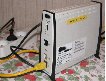 The units we tested are from a well know European manufacturer and are said to have a bit rate of 100 Mbps. The units were said to be prototype units, and did not carry any CE markings.
Narrow band PLC units (14 Mbps) from the same manufacturer have been CE-approved through a German test house.
3. Test setup for evaluating interference
- The regular antennas, normally used by the radio amateurs operating from their locations, were used at the 3 different test locations.
- All HF bands were checked for interference, with the PLC system notch both ON and OFF.
- The PLC system was idling in all cases. It is possible that more interference would be noted if the system was passing data.
 |
 |
 |
| Receiver noise floor | Antenna noise | PLC Interference |
To assess the level of interference, the following procedure was used:
- The receiver was adjusted to operate in a linear mode (AGC off, RF gain adjusted for sufficient sensitivity but preventing the receiver to become non-linear).
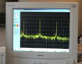
- The audio of the receiver was sent to the sound card of a PC equipped with an audio spectrum analyzer program (e.g. Spectra Plus or Spectrum laboratory by DL4YHF) sweeping 500 to 3000 Hz.
- The sensitivity of the sound card and receiver was adjusted (by changing RF gain) in such a way that the receiver noise floor (no antenna connected) was approximately - 80 to - 90dB. Receiver noise floor Antenna noise PLC Interference Next, the antenna was connected. The receiver gain was now adjusted in such a way that the atmospheric noise clearly shows on the spectrum (typically 5 to 10dB over the receiver noise floor on 28 MHz, and up to 30dB or more on 3.5 MHz).
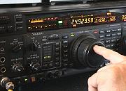
- Next a strong (typically S9+10) and steady carrier signal was tuned in. The level on the spectrum screen would typically read -20dB to -30dB. In order to check the linearity of the system between receiver noise floor and this signal level, a step attenuator is used in the antenna line. The signal level on the spectrum screen should follow the attenuator. In all 4 test sites the receiver settings were found to be linear within the range of interest, which means that the dB figures quoted are correct.
|
A number of photographs as well as video recordings were made. Some of these photographs are used in this report. Video recordings may be used in a video report to be issued later.
4. Initial tests The initial test site was the amateur radio station of ON4UN, located in Merelbeke, approximately 10 km south of Gent, in a semi rural environment. The installation at this initial test site was done by personnel of the potential large scale user. The two modems were installed in arbitrary places in the house. Both were connected to a laptop, in order to check modem performance. A number of settings can be made by adjusting the modem from a PC (each modem has a standard IP address).
During all the tests, the only modem setting that was altered was for switching the amateur band NOTCHES (provided by the manufacturer) in and out.
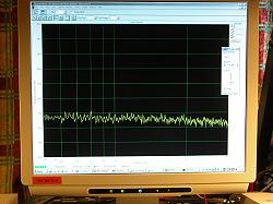
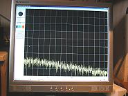
The initial tests showed extreme interference on all HF frequencies, ranging from 35 to almost 60db over the band noise. Band noise: - 75dB PLC interference: - 31dB.
The notches seemed to do a fairly good job, and on the bands with a relatively high band noise level, the interference was not audible any more. On the higher HF bands, such as 21 MHZ and 28 MHz, interference was still audible / visible near the band edges (see further under par. 5 and 6).
Next the susceptibility for interference by legally transmitted signals inside the amateur HF bands was tested. With a laptop connected at both ends of the link, throughput (rate, packet repeats etc) could be monitored.
Transmitting with 100 Watt on various bands on both CW and SSB clearly "killed" the system. Similar tests were repeated in more details in a later trial (see par. 10).
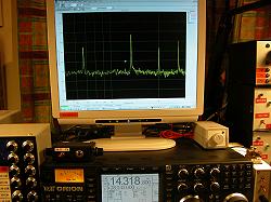
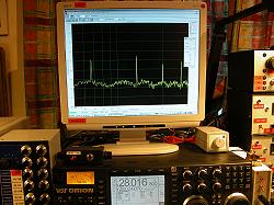
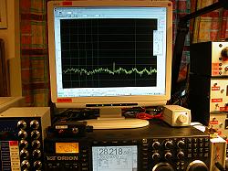
5. Field trial at ON4UN In the following week a more thorough check of the notch performance was done. We found that, depending on the band noise floor level, the modem signals were still very audible on the highest frequencies (21 and 28 MHz). Suspicion is that these are intermodulation products caused in the PLC equipment. The poor performance was most outspoken on the 20 MHz band. Notches were only "fully" effective from 28.5 MHz up. See pictures to the right. This poor notch performance was later checked and confirmed on a spectrum analyzer (see par 6). The tests were done on the 28, 21, 14, 7 and 3.5 MHz bands (no antennas available for the 10, 18 and 24 MHz bands). On 28 and 21 MHz two antennas were available: both 6 element yagis very close to the house at 18 and 21 m height (yagis overhanging part of the house) and a triband yagi (CX31) at approximately 50 m from the closest point of the house. There was very little difference in interference level between the two antennas, when the latter antenna was pointed to the house. On 14, 21 and 28 MHz all tests were done using the yagi located 50m from the house. On the 7 MHz band a 3 element yagi was used, partially overhanging the house (at 30m height). On the 3.5 MHz band a 4-square (4 element vertical array), with the centre about 20 m from the house was used. A top grade Ten-Tec ORION transceiver was used for the tests. Interference levels (above band noise) were greatest on the higher bands (28 and 21 MHz), obviously because the band noise on these frequencies is lower than on the lower frequencies. In practice it becomes impossible to work any station with signals less than S9 when the PLC system is operational with notches OFF. 6. Measurements at ON4UN We invited Mr Koos Fockens, (PA0KDF), member of the EMC committee of the Veron (Dutch IARU society), who has in the past done several measurements and tests in Holland, to do some level measurements at the test site of ON4UN. The full report is in attachment. ( |
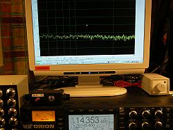 |
| Band noise: - 75dB | |
 |
|
| PLC interference: - 31dB | |
 |
|
|
Notch ON (28.218 MHz): interference 30dB over band noise
|
|
 |
|
|
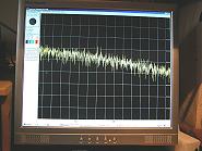
Notch ON (28.218 MHz): interference 13dB over band noise
|
|
 |
|
| ON4UN - 21 MHz: antenna noise: -75d | |
 |
|
| ON4UN - 21 MHz PLC noise: - 18dB |
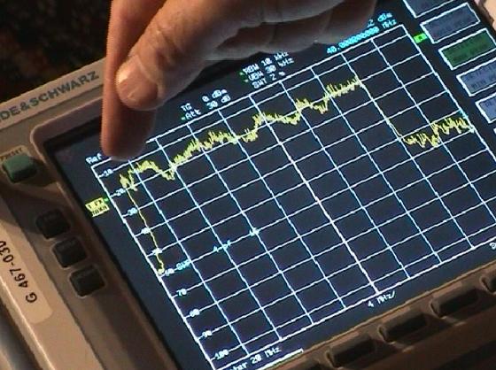 |
| Total spectrum 3 to 30 MHz, Notches off. Level equivalent to -50dBHz |
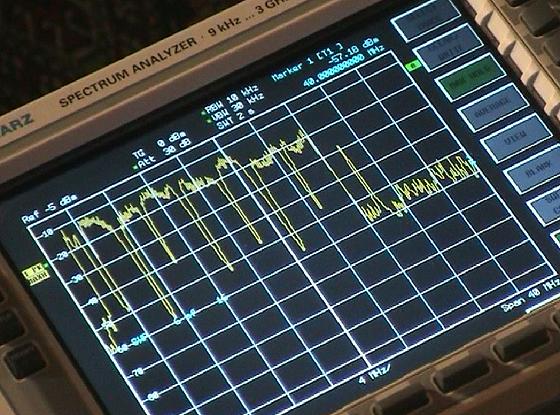 |
| Different amateur band notches. Notice that the 3.5 MHz- 4 MHz notch is less than 40dB; the 7 MHz notch dips at 45dB, while 10 MHz is only 25dB deep. This is because 10 MHz is a narrow band and apparently intermodulation products spill in the notch band from both sides |
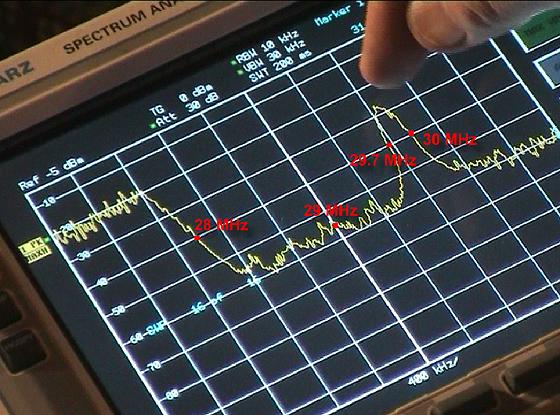 |
| The 28.5-29.7 MHz band notch: At 28.0 MHz the notch is only 20dB deep, in the middle of a slope. On the high end of the band (29.7 MHz) we see exactly the same phenomenon |
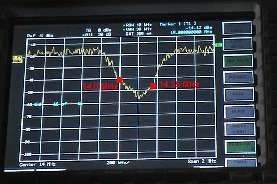 |
| On the 14-14.35 MHz band we see the same slope phenomenon. At 14.0 MHz we are only half way down the slope, and a similar situation exists on 14.35 although less outspoken. At 14.0 MHz the suppression is only approximately 25dB, at 14.25 it is 40dB |
Summary of the test results:
Differential mode level and spectrum measurements at the mains plug of the PLC modem indicate that the signal level exceeds CISPR 22B by not less than 40dB.
Notches do not function properly: signals are down 40dB or better in the centre of the band but a mere 20dB at the band edges.
Radiation levels exceed the NB30 specification by 20dB inside the house, 10dB along the outside walls of the house and up to 7dB some 100 m from the house.
 |
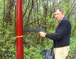 |
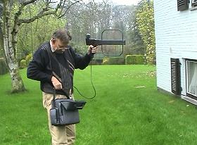
| Koos Fockens, PA0KDF, during the signal level measurements outside the house | Near a light pole over 100m from the house a level of 35dBuV/m was measured on 28 MHz (still 5dB over the NB30 limit) |
7. Field trial at ON4WW
A second field trial was done at the location of amateur radio station ON4WW (Mark Demeuleneere) in the outskirts of Sint-Denijs-Westrem, about 7 km South West of Gent. This is in a semi rural location, comparable to the location of the first test (at ON4UN). The antennas used at the ON4WW station are:
- 3.5 MHz: vertical (loaded antenna tower), 20 m from the house.
- 7 MHz: quarter-wave vertical, 25 m from the house.
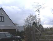
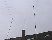
- 10 MHz through 30 MHz: various yagi configurations 13 to 15 m high on tower approximately 20 m from the house (see picture).
The same tests, as done at ON4UN's station were repeated, band by band and identical interference patterns were noted, be it that the strongest interference, in the 28MHz band was actually 60dB over the band noise level, even slightly higher than at ON4UN.
The poor performance of the notches on the higher bands near the band edges was also noticed. This trial confirms in all respects the observations made at ON4UN.
 |
 |
 |
| A 12 m tower (top mast 16m), approximately 20 m from the house, supports various yagis for 10 through 29.7 MHz | A YAESU FT1000MP was used at ON4WW, with gain adjusted for linear response | A YAESU FT1000MP was used at ON4WW, with gain adjusted for linear response |
8. Field trial at ON5OO
 |
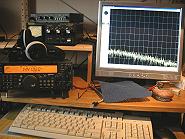 |
 |
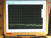
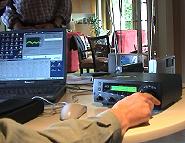
| Vertical antenna (and dipole) used at the ON5OO station | TS570D transceiver used by ON5OO | The audio spectrum scope (sweeping 500 Hz to 2500 Hz) shows the receiver noise (no antenna connected) |
|
The amateur radio station ON5OO (Jacques Debouche) is located in the outskirts of Brussels, in a very densely built up area.
The antenna is a Cushcraft all band vertical on the roof, with the base a few meter only above the apex.
The main difference between testing at a semi rural location (ON4UN, ON4WW) and this location is the very high band noise level, caused by local man made noise.
On 14 MHz the noise level is some 35dB above the receiver noise, as compared to typically 10dB at the semi rural locations of ON4UN and ON4WW.
One modem was located about 5 m under the vertical antenna on the 1st floor, the other one on the ground floor about 7 m away from the first modem.
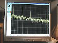
The level of the PLC interference is approximately S9 on all frequencies between 10 and 30 MHz at this location. Despite the high noise level in the city, on 28 MHz the PLC signal is clearly visible near the band edge inside the band, showing largely insufficient notching, even for such high level noise areas.
In addition to the aspects of interference on the amateur bands, some system performance tests were performed whereby the impact of radio transmissions on the PLC link as evaluated (see par. 10).
|
 |
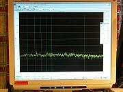
| Band noise on 14 MHz (some 35dB above the receiver noise!) | |
 |
|
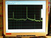
| PLC signal (AM position) peaking approximately 30 - 35dB over the band noise. |
9. Broadcast receiving tests
Initial contacts with the Belgian National broadcasters yielded little interest in this project from their behalf. We therefore contacted RN (Radio Netherlands), who were very interested to participate in a field trial.
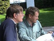
Two of their experienced engineers came over to do some BC reception field testing in an (in house) PLC environment. What follows is the report made by E. Goddijn and L. van der Woude, from RN.
 |
 |
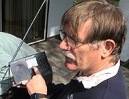 |
| Experts in the reception of short wave broadcasting from RN (Radio Netherlands) gratefully accepted to take part in the PLC test exercise | Left: Ehard Goddijn, right: Leo van der Woude from RN | AM reception tests were performed on a number of quality short wave receivers outside and inside the house |
| Report on visit Merelbeke, Belgium concerning the effects of PLC equipment on SW-reception. Present: John Devoldere, Chairman Union Belgian Radio Amateurs (UBA) Gaston Bertels, Chairman Eurocom Working Group Ehard Goddijn, Frequency Manager, Radio Nederland Wereldomroep Leo van der Woude, Coordinator Shortwave Distribution (RNW) Objective: To determine the effects of 2 PLC modems on the reception of Shortwave transmissions in real terms. Context definition: Two PLC modems were placed in two rooms next to each other (15m apart). Furthermore they were used only in a stationary mode, the observations were made with no data transport over the modems. The first observations took place outside the house. The second set observations took place inside the house. The observations were made on Monday April 11th, 2005 between 10:00 and 14:00 UTC. The geomagnetic conditions were stable.
The used consumer receivers for the AM-reception were:
The used receivers for DRM-reception were:
Experiences We were faced with a noise on all, by Short Wave broadcaster used frequency bands. The noise was detected with peaks at a distance of 10 to 15 kHz. It was a disturbing rattling sound. The noise was the strongest on the 6 and 7 MHz band. This goes for all the receivers we used. The noise is not observed directly after turning on the modems, they take about a minute to start-up the communication. AM-reception Even with the Deutsche Welle transmission on 6075 kHz, one of the strongest signals in the 49m band, the noise was annoying. Only at a distance of 25m from the house, in the open field, the noise was not annoying anymore. The 5955 kHz transmission from Radio Nederland Wereldomroep just happened to be in between two noise peaks so had less problems with the noise. However the transmission of Croatia on 6165 kHz and Medi_1 on 9575 kHz from Morocco, two reasonable well received programs became by the rattling noise ill-listened to. Also in this case only on a distance of 25 m both transmissions became listenable again. DRM reception The Deutsche Welle transmission on 9655 kHz got a 5dB lower SNR value after starting up both the modems. (On the receiver observed). With the RTL transmission on 5990 kHz the SNR got 7dB lower, for the RTL transmission on 6095 the Signal to Noise value got a 10dB lower. A difference in disturbance was observed when even one modem was started, only with less effect. When a transmission had a critical SNR more interruptions of - and even complete disappearance- of the DRM program was observed. Conclusions When PLT is implemented on a large scale we foresee large problems with respect to the reception of Shortwave signals in general and the Shortwave reception of programs of international broadcasters in particular. (Freedom of expression, (Article 10), information with calamities). Possibly with other Modems and with maximal data transfer over the modems the results shall be different, we expect them to be worse. Following additional observations will need to prove this. We have experienced this as a wrongful use of this part of the frequency spectrum on the power lines as they are not designed for this purpose. They radiate the noise too much to other users and therewith interfere too much in the reception of Shortwave programs. |
 |
 |
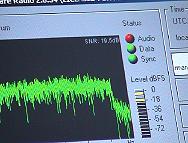 |
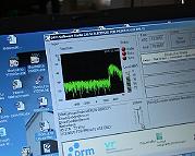
| Substantial time was spent on evaluating the effect to DRM (digital radio) reception | During tests on DRM signals that were received perfectly without PLC | The sound dropped out or the link was totally lost with the PLC system operational |
10. System performance tests
|
Jacques Debouche, ON5OO, a professional telecommunication expert, also ran a few checks on the PLC performance when installed near an amateur radio station.
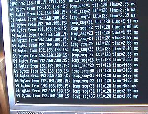
In one test setup, two laptops were connected to the two modems, and one laptop pinged the address of the other modem.
Using very low power (5 W) the ping return time went up in the thousands of ms (see picture to the right).
With a little more power the PLC system would simply hang. Next a video was sent from one laptop to the other, using a shared DIVX. This demonstration was very spectacular.
|
 |
|
| During transmission on the HF bands with as little as 5 Watts of power, the transmission time (normally about 2 - 3 ms) went up a factor one thousand! |
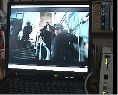 |
Transmitting with typically 5 Watts into a vertical multiband antenna, one would first see the sound drop out and then watch a still picture as long as the station would transmit (an ideal way of freezing a movie scene). It appears that this system will not perform at all in an amateur radio station environment.
Whereas these tests were done where the transmit antenna was fairly close to the PLC systems (5 to 10 m), one has to consider that the PLC links suffered from interference with power levels as low as 5 Watts.
In many other situations, stations could be using high gain antennas (up to 10dB or more gain as compared to the vertical in this case) and transmit with power up to 1 KW (13dB more than the highest power used in these tests at ON5OO). At the station of ON4UN, 100 W transmitted from a yagi antenna 50 m from the house also "killed" the link.
|
|
| Frozen picture during video transmission across the PLC link. Notice from the modem pilot lights that synchronization has been lost and that there is no communication at all at the time the picture was taken |
You are missing some Flash content that should appear here! Perhaps your browser cannot display it, or maybe it did not initialise correctly. Here is a video version of the above picture.
|
11. Conclusions
- The level of the differential mode conducted signal injected in the AC receptacles in the house exceeds the CISPR 22B spec with not less than 40dB.
- At the ON4UN test site, the radiation field strength exceeds the NB30 limit with 30dB inside the house, with 10dB outside the house at approximately 3 meter from the house, and with up to 7dB at 100 m from the house where the PLC system is installed.
- Tested at 3 different test-sites, the PLC system creates signals over the entire HF spectrum from 3 to 30 MHz (notches not enabled). These signals are ranging from 35 to 60dB higher than the residual band noise. This makes it in most cases impossible to use the HF bands for two-way communications. In amateur radio terms, with an in-house PLC system operating nearby, the S-meter sits at around S8 to S9+10dB on a "clear" frequency, all through the HF spectrum.
- The unit tested had provision for enabling so called notches in the amateur bands. These notches are not always doing a good job, in as far as the rejection is a mere 20dB at the band edges, and 40dB in the centre of the band. 40dB all over would be OK in many circumstances (except in very quiet environments). The poor performance at the band edges is likely due to intermodulation products caused by the system carriers near the notch edges. A field trial in remote rural locations, where band noise could be expected to be a further 10dB down (depending on band) as compared to what we experienced at the semi rural locations of ON4UN and ON4WW, the performance of the notches could be even less effective. In such areas deeper notches and "cleaner" notches would be essential. Based on the results obtained with the prototypes units, it seems that the notches should be made 200 kHz wider at each notched band edge (400 kHz in total for each notched band).
- From a PLC system performance point of view, the system is extremely vulnerable and transmissions inside the radio amateur bands with as little as 5 Watts to a simple vertical antenna can simply kill the link. This was also true with the notches enabled.
- Shortwave broadcast reception is also impaired by the system. The signal to Noise ratio on DRM reception decreased with up to 10dB (and more) on some stations, and turned a perfect reception into total silence!
A field trial was witnessed by high ranking personnel of Nato and the Belgian Air Force. The observers were no less than flabbergasted when confronted, in a real life situation, with an in house PLC system rendering the HF bands as good as useless.
This report concerns testing and real life experiences with a high speed PLC modem of one particular brand and model. It is not our intention in any way to harm neither the manufacturer nor the lender of the units; this is why neither the manufacturer nor the lender are identified in this report. We believe that the results are likely to be typical for other similar high speed in house PLC modems.
We are convinced that deploying these PLC systems is looking for disaster for the PLC system user point of view.
It is obvious that radio amateurs cannot be held responsible for interference to such (extremely vulnerable) systems.
Although correctly working notches may provide a solution for the radio amateur community in many cases, we have to insist that the regulator makes it mandatory for any such equipment sold that notches of at least 40dB deep over the entire amateur radio bands be operational at all times. They should NOT be switchable by the end user. But from a more generic point of view, it is clear that any of the frequencies in the HF spectrum where no notches are present, are rendered useless except for maybe super power transmissions over short ranges. Notching more than maybe 10% of the spectrum does not look reasonable either from a PLC system bandwidth point of view.
Whereas the amateur radio community is convinced that CISPR 22B and NB30 are not stringent enough to protect the amateur service, the fact that during these field trials both injected signal levels (injected into the mains) and radiated signal levels largely exceed the limits specified by the above specifications, makes this particular in house PLC system completely unacceptable from different points of view.
It will be interesting to see if the manufacturer achieves in having this equipment CE-approved.
12. Further work
We plan to do similar testing with narrowband in house systems (14 Mbps rate). Such modems are currently available in many shops. We understand several shops, however, have stopped carrying these units because of the many problems associated with these.
13. Acknowledgements
We would like to thank
- The lender of the units for giving us the opportunity of testing the high speed PLC modems.
- Leo van der Woude and Ehard Goddijn from Radio Netherlands for their tests regarding PLC interference to HF broadcast service.
- Ir. Kwie-Sing Kho from Nato and Major Johan Holvoet from the Belgian Air Force for their help and advice.
- Koos Fockens, PA0KDF, for the measurements according CISPR22B and NB30.
- Jacques Debouche, ON5OO, for his PLC performance tests.
- Mark Demeuleneere, ON4WW, and Jacques Debouche, ON5OO, for their field tests on interference to the amateur radio bands.
June 22, 2005
John Devoldere, ON4UN, President UBA, ON4UN [at] uba [dot] be
Gaston Bertels, ON4WF Chairman Eurocom, ON4WF [at] UBA [dot] be